Centrifugal Chiller GXG Series

Hitachi GXG Series Centrifugal Chillers Show a Remarkable Energy-Saving Effect and Are Friendly to the Global Environment
| 2-stage Compression Cycle |
|---|
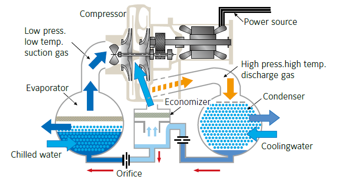
| To improve compressor efficiency, refrigerant economizer is added with 2-stage compressor equipped with 2 impellers, as shown in the drawing below. In this case, the refrigerant goes through two expansion devices. When the refrigerant goes through the first device, some of the refrigerant flashes, or become a gas. |
| The flashed refrigerant is introduced to the compressor between the two stages. In the one-stage compressor cycle without the economizer, all refrigerant flows in the cycle. Comparatively, in the 2-stage compressor cycle the part of the refrigerant is bypassed from the economizer to the 2-stage impeller. |
| 2-stage Centrifugal Chiller Cycle |
|
| Surge Protection |
|---|
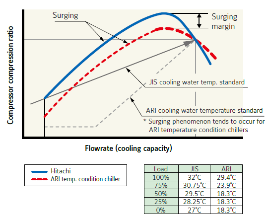
| Adopting strict criteria specified in JIS for stable operation under high cooling water temperature. 3D 2-stage impeller enables stable operation even at low cooling load or high cooling water inlet temp. which prevents occurrence of surge. |
| Compressor characteristic comparison |
|
|
* This figure shows general characteristics and does not provide any guarantees as to the performance.
|
| New Type Economizer |
|---|
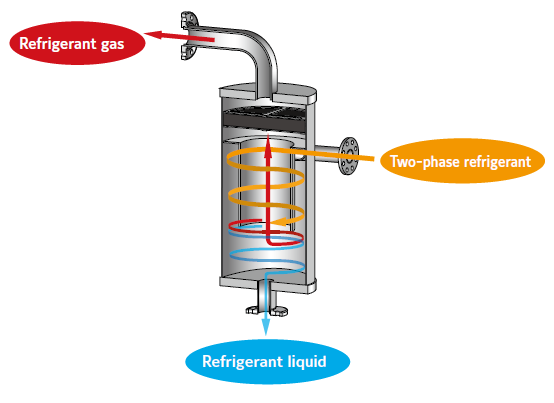
| Improvement of vapor-liquid separation performance and significant downsizing are realized by the use of Newly-developed economizer. (cyclonic system) |
|
| Compatible with BMS |
|---|
| Chiller control panel is equipped with RS485 communication port and compatible with Building Management System through MODBUS RTU protocol. |
| Easy Operation with Touch Panel Type Control Panel |
|---|
| 10.4 inch color touch panel screen |
| Monitor various operating data |
| Indicate trend graph during operation |
| Trend data for max. 40 hours. (Updated every 1 hour) |
| Indicate and store operation history for the past 12 hours (Updated every hour) |
| Indicate and store failure and alarm history (latest 6 times each) |
| Show Handling Guide in case of failure |
| Automatic restart function after instantaneous power failure (Option) |
| Multilingual Languages Indication (Japanese, English, Chinese [Simplified, Traditional], Portuguese) |
| Download 3-month operation date to USB memory |
| Global Warming Prevention | |
|---|---|
|
Global warming refers to the phenomenon of global rising in average atmospheric temperatures due to increased volume of CO2 and methane as a result of burning fossil fuels such as petroleum and coal. The 1995 IPCC* Report predicted that if the emission of CO2, etc. continued as it was, the atmospheric temperature would rise by as high as 2°C by the end of the 21st century and, as a result, the sea level would rise by apporoximately 50 cm from the present level. In such circumstances, it is more strongly required to save the energy consumed by air conditioners in order to cut CO2 emission.
* IPCC: Intergovernmental Panel on Climate Change
|
|
| Ozone layer Protection | |
Chlorofluorocarbons (CFCs) diffusing in the stratosphere are exposed to ultraviolet rays to be decomposed, separationg chlorine atoms. It is said that separated chlorine atoms combine with oxygen atoms in ozone to destroy the ozone. Because HFC134a has no chlorine atoms, it does not destroy the ozone in the atmosphere.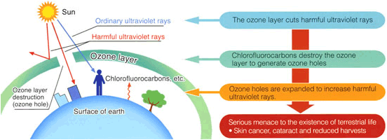
|
Hitachi's High Technology and Rich Experience Realized High-Efficiency Chillers
By employing a three-dimensional blade impeller (2 stages), economizer subcooling cycle and high-performance heat exchanger tubes, Hitachi succeeded in greatly increasing efficiency.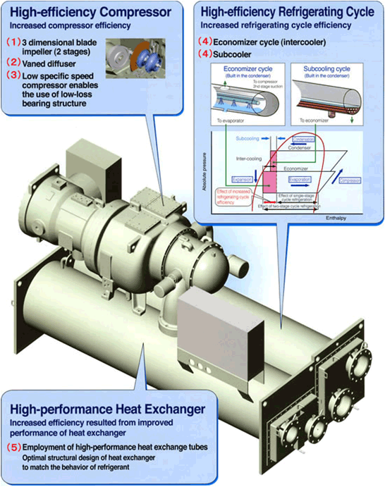
|
||
| High-Efficiency Compressor | ||
|---|---|---|
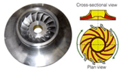
| (1) Three-dimensional blade impeller (two stages) | ||
|
The impeller with three-dimensional curved blades, which is low in internal flow loss, is employed to realize high efficiency in a wide operating range. The impeller is made of aluminum alloy with sufficient strength and manufactured by precision vacuum casting to give it ideal flow passages. | |
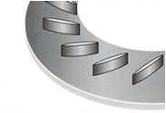
| (2) Vaned diffuser | ||
|
For the diffuser, which is used to convert the velocity of refrigerant gas accelerated by the impeller into static pressure, vanes of small chord-pitch ratio and a high pressure recovery ratio were developed by computer design to realize high efficiency. The ideal diffuser shape, which is implemented by NC machines, realizes stable operation in a wide range from high to low load conditions. | |
| (3) Low-loss bearing structure | ||
| Due to the employed 2-stage compression system, the speed of the compressor can be lowered, which results in reducing bearing loss. | ||
| High-Efficiency Refrigerating Cycle | ||
| (4) 2-stage compression economozer and subcooling cycle | ||
|
With a vapor compression type chiller, the "heat of evaporation" that is generated when the state of the refrigerant changes from liquid to gas is used to cool chilled water in the evaporator. The lower the temperature of the liquid refrigerant that flows in the evaporator, the greater the heat of evaporation and the lower the quantity of circulated refrigerant. As a result, the power of the compressor is reduced and theoretical cycle efficiency increase. Economizer (intercooler) utilizes the self-cooling effect of refrigerant to lower the temperature of the refrigerant almost to the middle of condensing and evaporating temperatures. The employment of the 2-stage compressor makes it possible to employ the economizer cycle and thus increase efficiency. By employing the subcooler (a compact cooler built into the lower part of the condenser) to cool the liquid refrigerant, which is liquefied in the condenser, by means of cooling water, theoretical cycle efficiency is increased further. 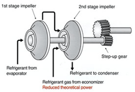
|
||
| High-Performance Heat Exchanger | ||
| (5) Evaporator and condenser | ||
| The high-performance heat exchanger tube is used in the evaporator and the condenser, and the arrangement of tube banks is optimized as well to improve the performance of the heat exchanger. | ||
Realized High Operability and Comfort, such as Wider Operating Range and Low Noise
| Wider Operating Range | |
|---|---|
|
|
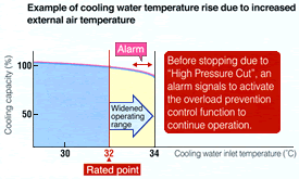
| (1) Coutinuously operable without worry even on very hot days | |
|
Stable operation continues even when cooling water temperature rises in hot summer and condenser pressure rises due to proceeding tube fouling. |
| (2) Low-load operation is available throughout the year without special devices | |
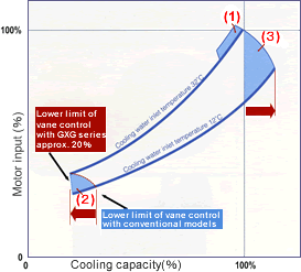
| Conventionally the lower limit point for capacity control has been set mechanically, so that the capacity at the lower limit point increases in intermediate seasons or winter. With the GXG series, operation is stable up to 20% even at low cooling water temperatures, without any special devices (hot gas bypass valve, etc.), due to microcomputer control. | |
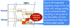
| (3) Even in seasons where external air temperature is low, the expanded operating range of single unit chiller assures a high energy saving effect | |
|
While conventional models require a controlling coolng water inlet temperature of 20°C or higher, GXG series can operate up to a cooling water inlet temperature of 21°C, expanding further the capacity range. |
| Low Noise | |
| The fluid dynamic design of the compressor interior was optimized to achieve low noise. Because a 2-stage compressor is employed, speed is lowered and noise, especially high frequency noise, is cut remarkably. | |
High-Reliability and Minimized Maintenance Necessity


